"CNC Desktop Lathe"
About the Class
This course focuses on the principles of modeling, design, integration, and best practices of machine elements (bearings, springs, gears, cams, and mechanisms) with emphasis on application of core mechanical engineering principles (solid mechanics, fluid mechanics, manufacturing, and computer simulation) in the context of developing a real world machine.
Project information
- CategoryCourse project
- Project dateSpring 2025
- Skills usedAnalysis, Modeling, Fabrication, FEA, Integration, Experimental Testing
System Highlights
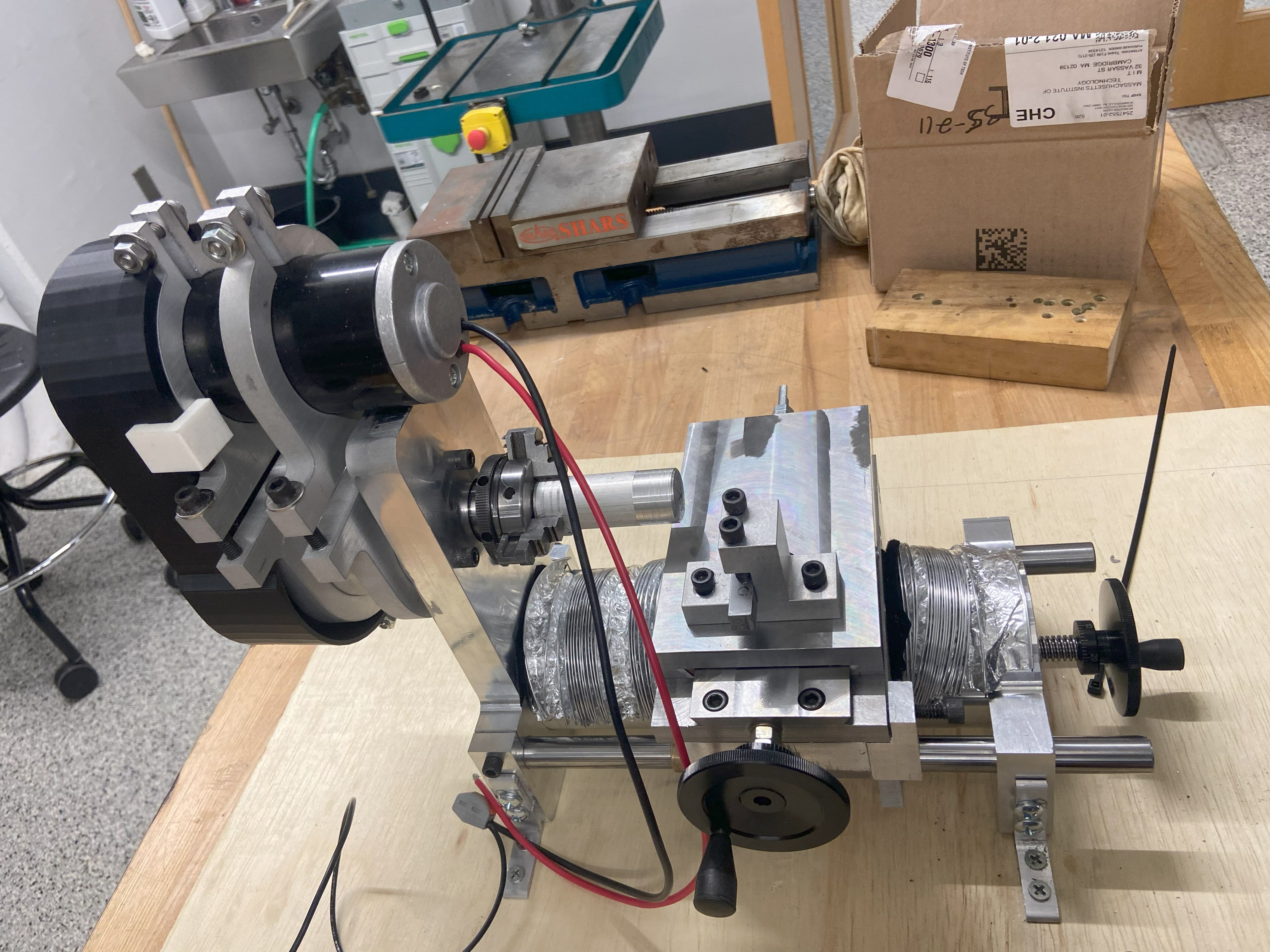
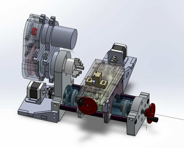
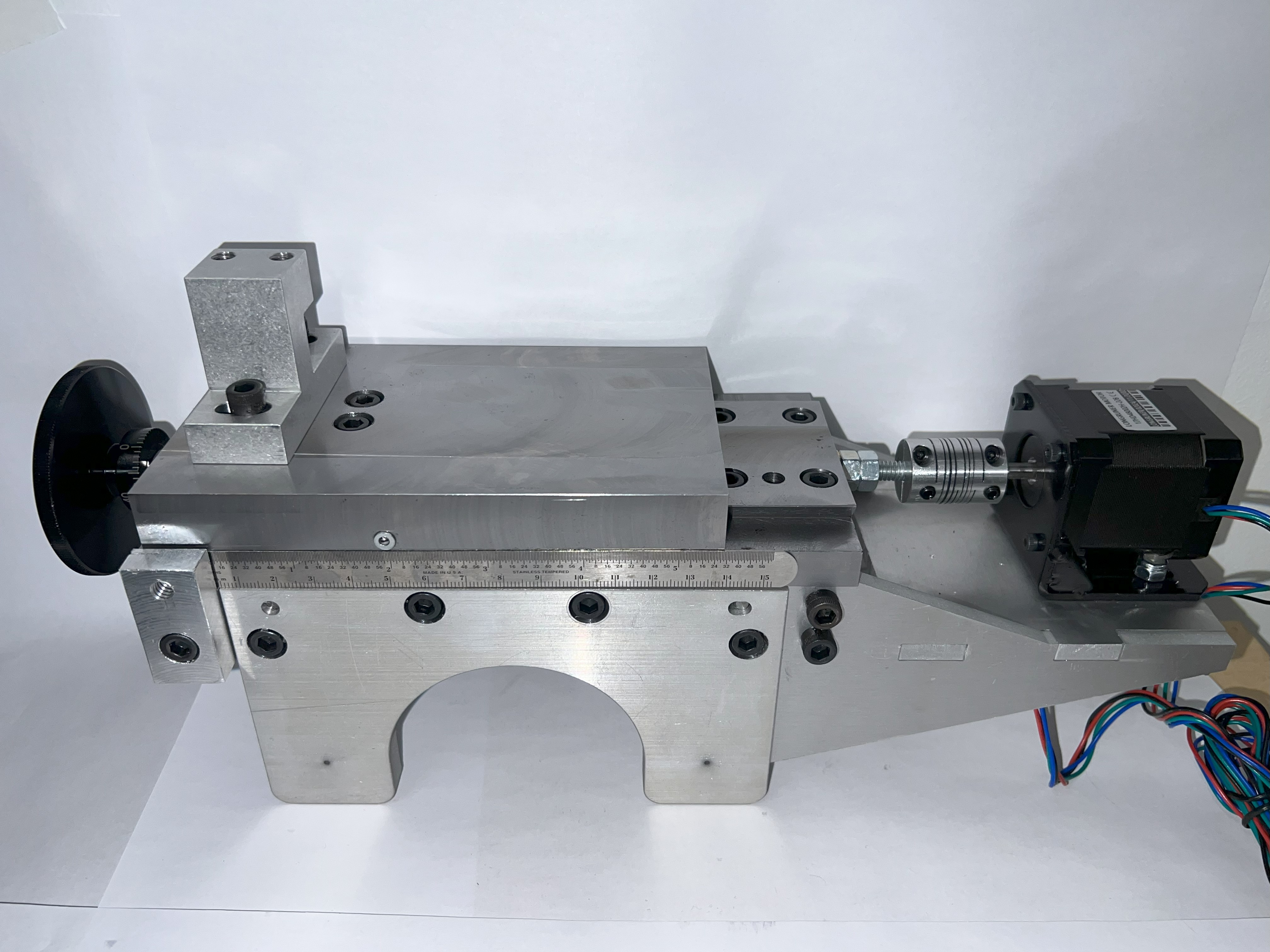
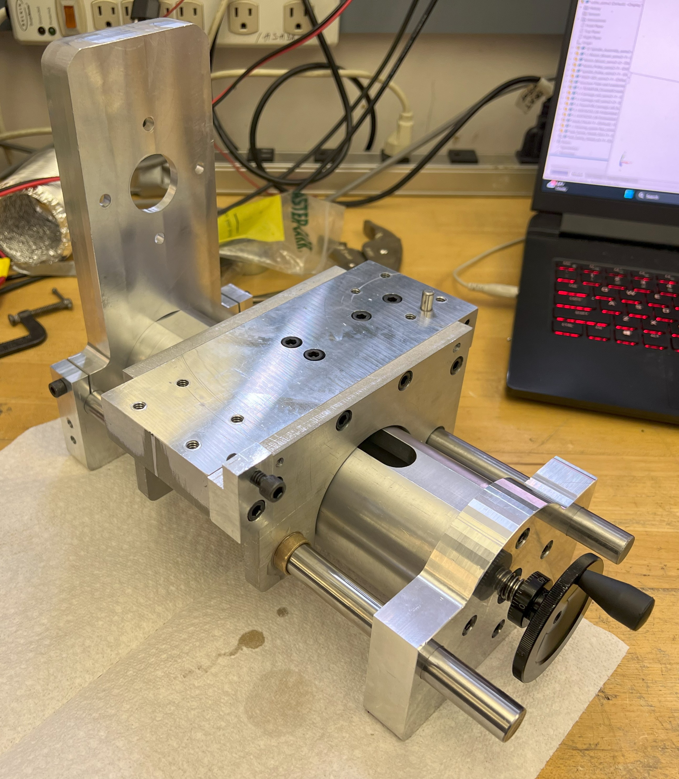
Big Bertha consists of four main subassemblies: spindle, cross slide, z drive, and CNC integration. In terms of key performance, Big Bertha has a precision of 50 microns, cutting resolution of 9 microns (when accounting for backlash), cutting envelope of 3 in. length x 1.5 in. diameter, and a maximum material removal rate of 1.13 in^3/min
My contribution
The team consisted of 5 graduate students. I was responsible for FEA for the first half of the semester, focusing on the stiffness and thermal analysis and FEA validation of the spindle shaft and assembly. In the second half of the semester, I focused on CAD, leading the integration and debugging of the x-drive (carriage assembly) and the z -drive (z-tube assembly). I was also responsible for the analysis, modelnig, CAD, FEA, fabrication, and testing of the "dancing queen" flexure, which is the component responsible for connecting the x and z drive.
Reflection
This course gave me a deeper appreciation for how modeling, analysis, and fabrication work together to build a reliable machine tool. It pushed me to balance theory with hands-on decision-making. Major lessons I took away include:
- Measure Twice, Cut Once: There were multiple occasions where even a slight mistake when making a part whether in the design, process plan, or machining caused a butterfly effect to many other things. If we slowed down a little bit and checked ourselves, we could save time and effort by not having to remake parts.
- Model like it's New York Fashion Week: If a part, system, or function wasn’t modeled, we were essentially guessing at its performance. Without concrete understanding of the guiding principles and relationship between design and performance, any errors in operation left us with no clear path to iterate or fix the design. Even simple back-of-the-envelope calculations before machining are essential—they guide design decisions, set performance expectations, and provide the framework for making informed changes once the system is in use.
- When in Doubt Ask Wade (Head of Machine Shop): Your machine shop head/manufacturing engineer in the real world should be extremely knowledgeable about the shop that they work in. They are there to help, so make them happy by making their lives easy and taking their advice.
- Communication is Key: Having proper communication with your teammates and mentors is vital to both making sure you provide an adequate product and that you can do so within the allotted time frame without burning yourself out.
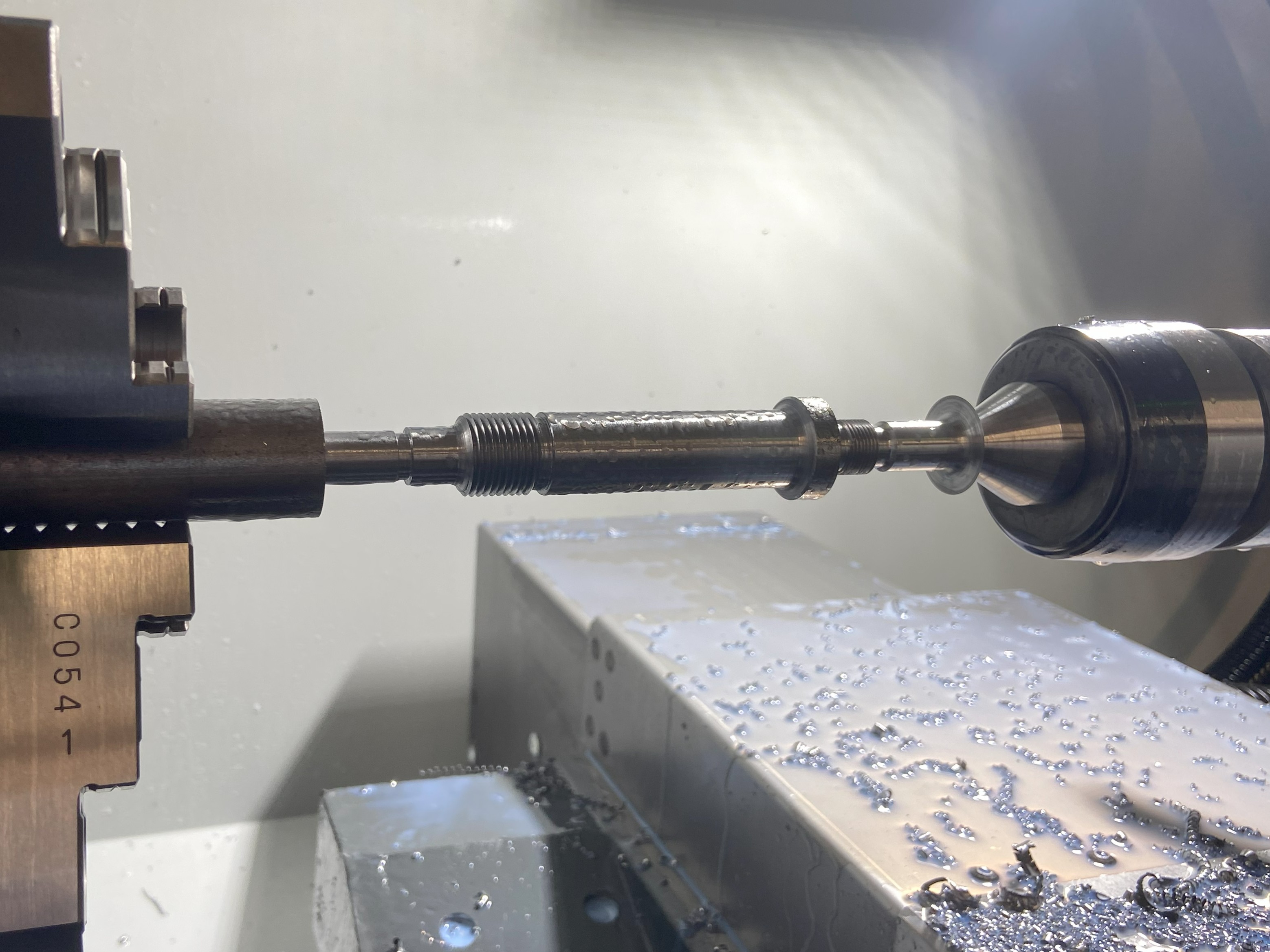
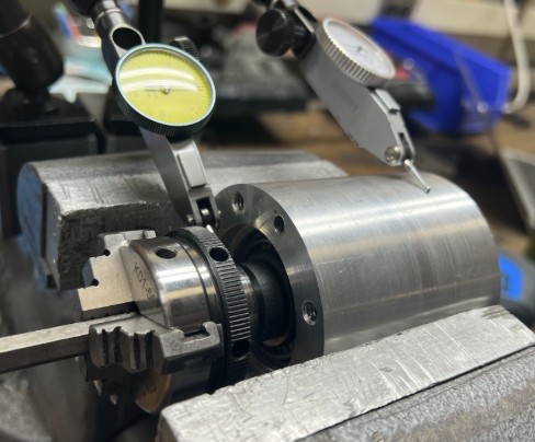
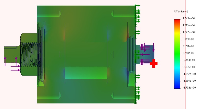
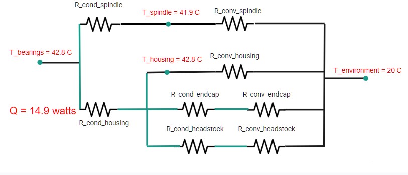
Spindle Assembly
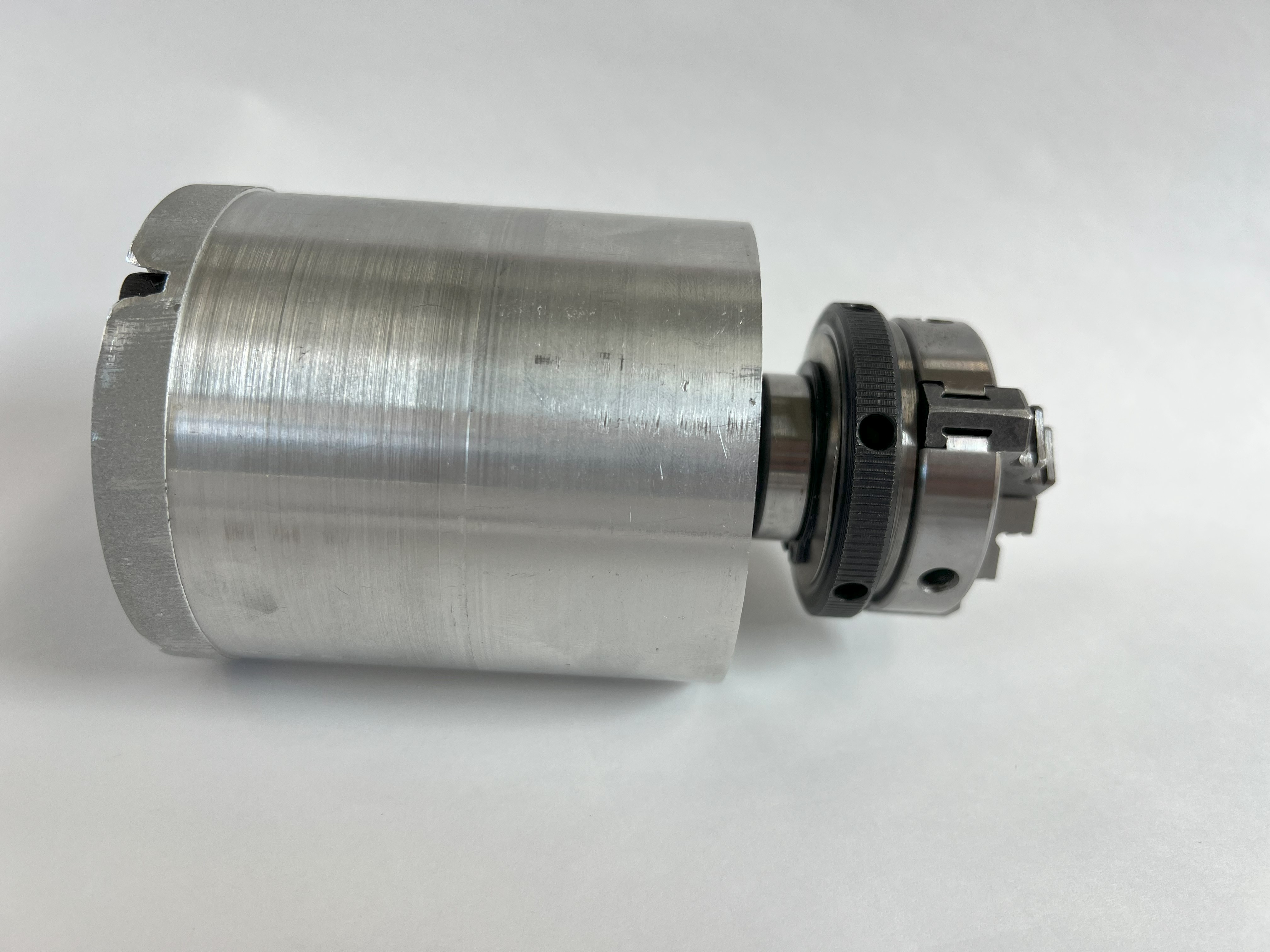
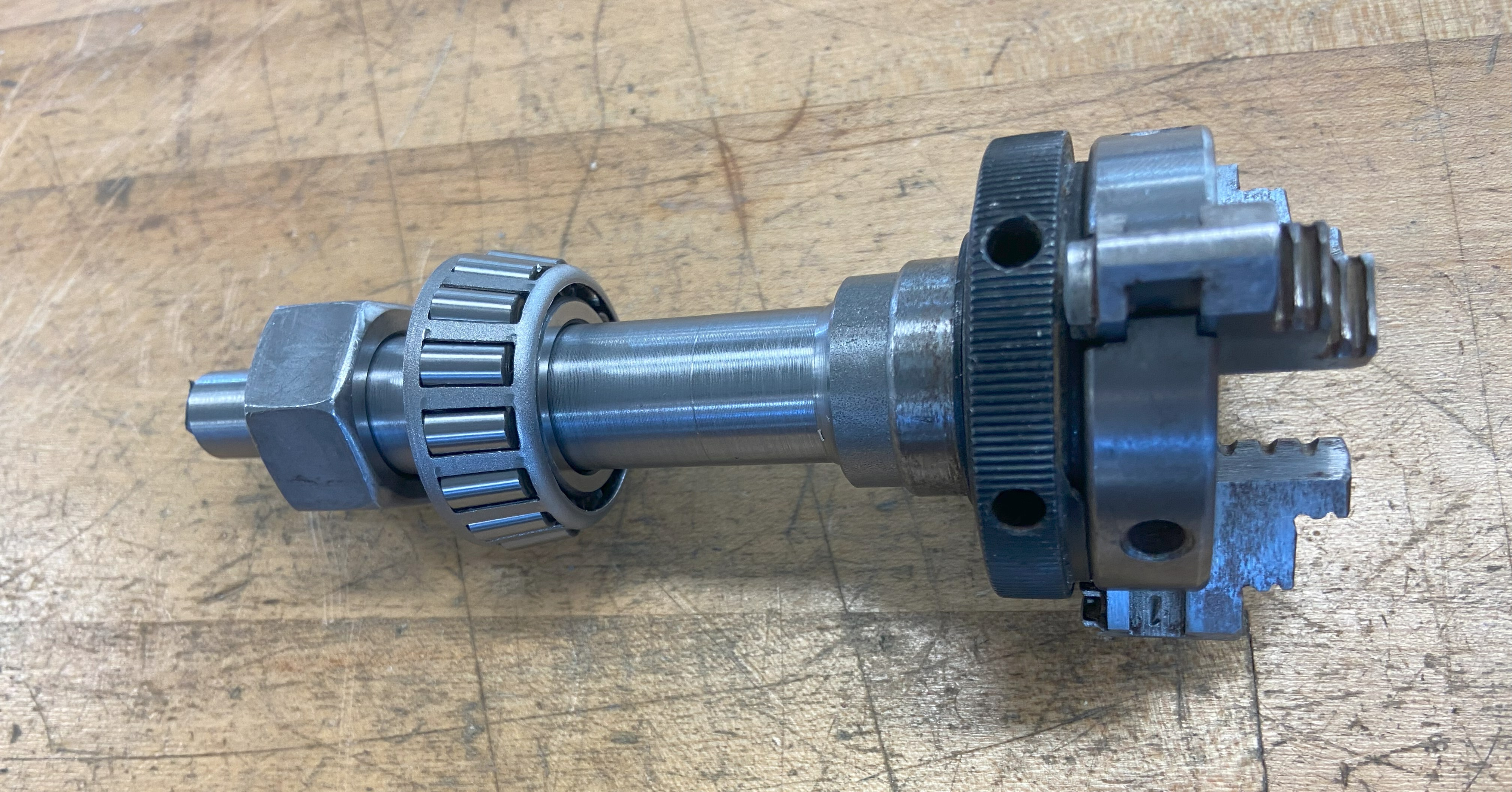
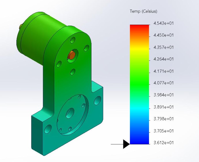
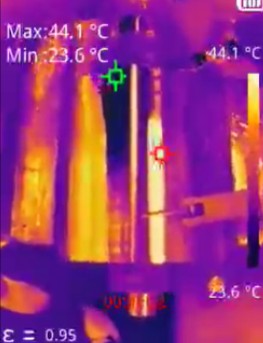
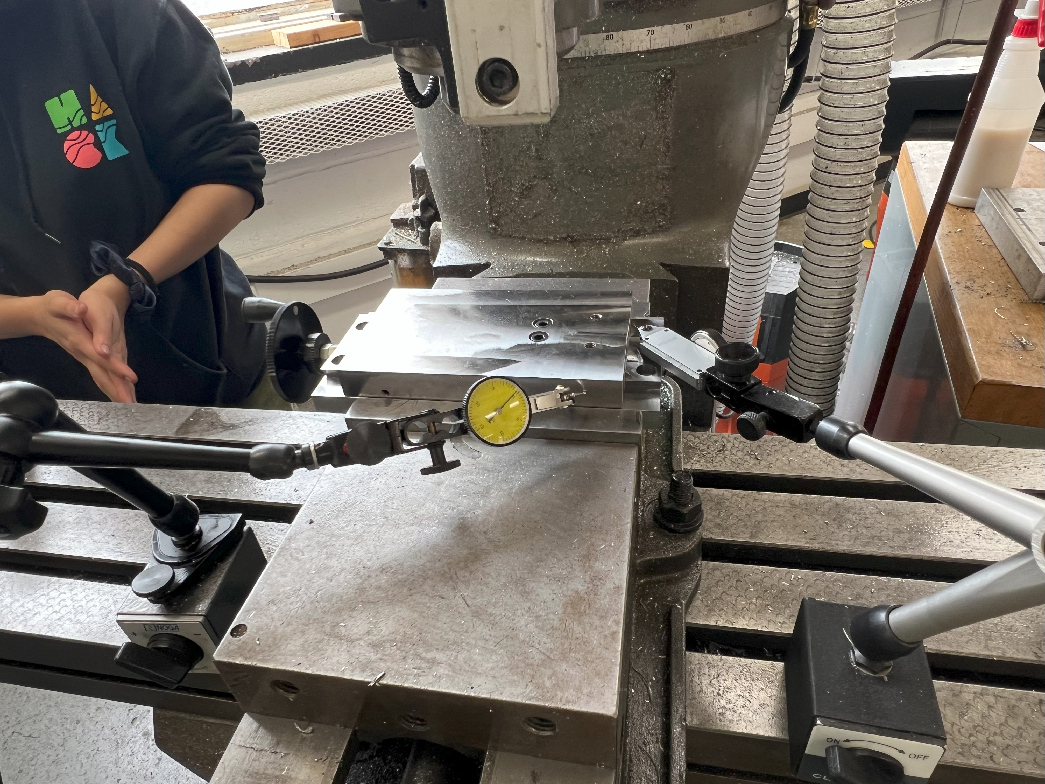
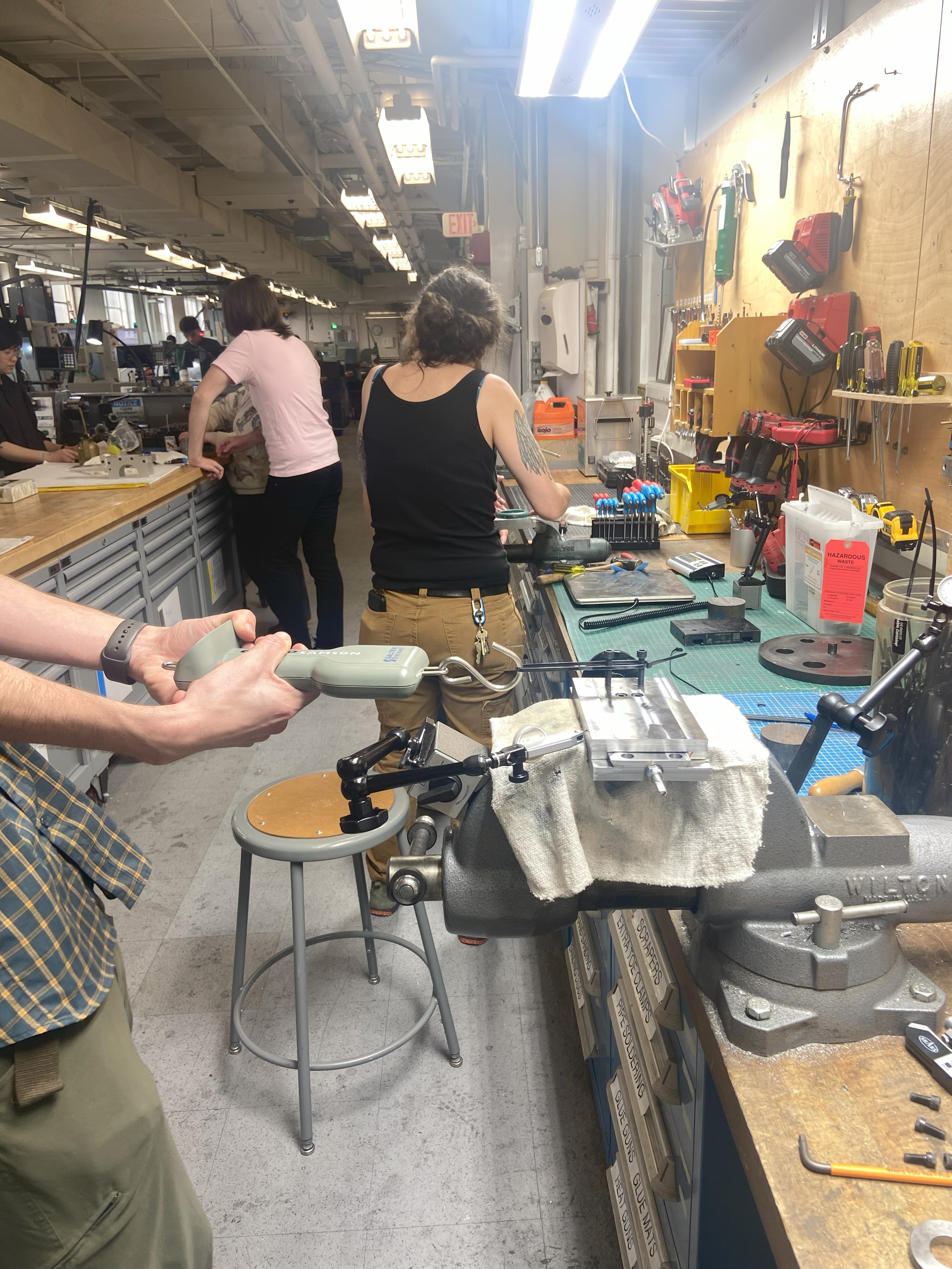
The spindle consists of the housing, shaft, bearing, end cap, seals, and chuck. We defined functional requirements on the spindle speed, load capacity, stiffness, runout, and operating temperature. We performed stiffness calculations and FEA validation for our initial design, and measured our final radial and axial stiffness to be 2.00 N/μm and Axial: 2.80 N/μm respectively. For the thermal analysis, I set up an equivalent resistance network validated with FEA and used a thermal gun to confirm that the housing would not get too hot to touch, and the bearings would not experience thermal runaway. In the model, FEA, and testing we found that the maximum temperature was around 45 °C. The spindle has an accuracy of 6.0 ± 2.5 microns of runout without the chuck. This was determined by using dial indicators set up at both the tip of the spindle and the inner neck of the chuck. The chuck initially had run out of >400 microns. To improve the chuck to meet precision specifications, we used an aluminum block to preload the chuck jaws and bored out the jaws of the chuck. After conducting the Donaldson Reversal Method to separate the error of the workpiece from the error of the chuck, the measured runout was 17.5 ± 2.5 microns.
Cross Slide (X-Drive)
The X drive consists of the male and female dovetail, gib, tool holder, anti-backlash lead nut, carriage, stepper motor, and angle adjustment screw. We defined the functional requirements for resolution, stiffness, and torque-to-turn as these directly relate to the movement of the tool tip. The cross slide achieved a resolution under 10 microns, stiffness of 5.3 N/μm in X and 7.9 N/μm in Z, and a torque to turn of only 2.5*10^-2 N-m. The resolution was measured by the backlash of the cross slide assembly and the accuracy of the CNC stepper motors. The CNC stepper motors had a resolution of 0.4 microns, which left a margin of 12.5 microns for backlash, given the team's funsctional requirements. The backlash was calibrated to 9.0 +/- 2.5 microns by tightening the cross slide flexure/anti-backlash device around the leadscrew, giving a total error under 10 microns and within spec. The stiffnesses were calculated using dial indicators and measuring deflections of the structure given a set load. The last requirements was the x drive should still be able to function even with a person standing on it!
Z Drive
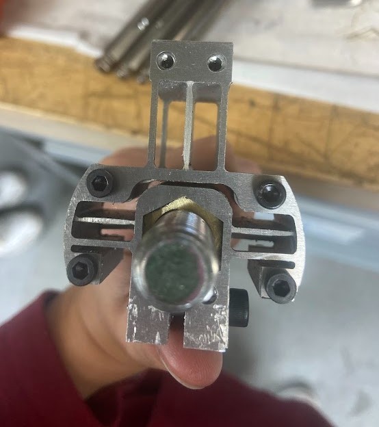
The Z drive consists of the carriage, rails, dancing queen flexure, rail flexure, and structural tube. The dancing queen flexure and rail flexure are designed to remove any over constraints from the two rail flexure, the carriage lead screw, and the carriage skirts. The dancing queen flexure was particularly challenging to design because it needed to be compliant in X, Y, θx, and θy, to account for misalignments while remaining stiff in Z and θz to accurately transmit z motion the tool tip. I did the analytical model, CAD, FEA, fabrication, testing, and integration of the dancing queen flexure and Z-drive assembly. Overall, the Z drive had a resolution of 10 microns, Z-axis stiffness of 3.4 N/μm, a torque-to-turn of 2*10^-1 N/m, and angular error less than 0.5°. Similar to the X-drive, another class requirements was the Z drive needs to function with a person standing on the carriage.
CNC integration
For the CNC integration, we used NEMA 17 motors connected to the x and z lead screws. We used an online kit for the electronics and GRBL firmware to convert cutting commands to g code.
Death Test and Team Pics!
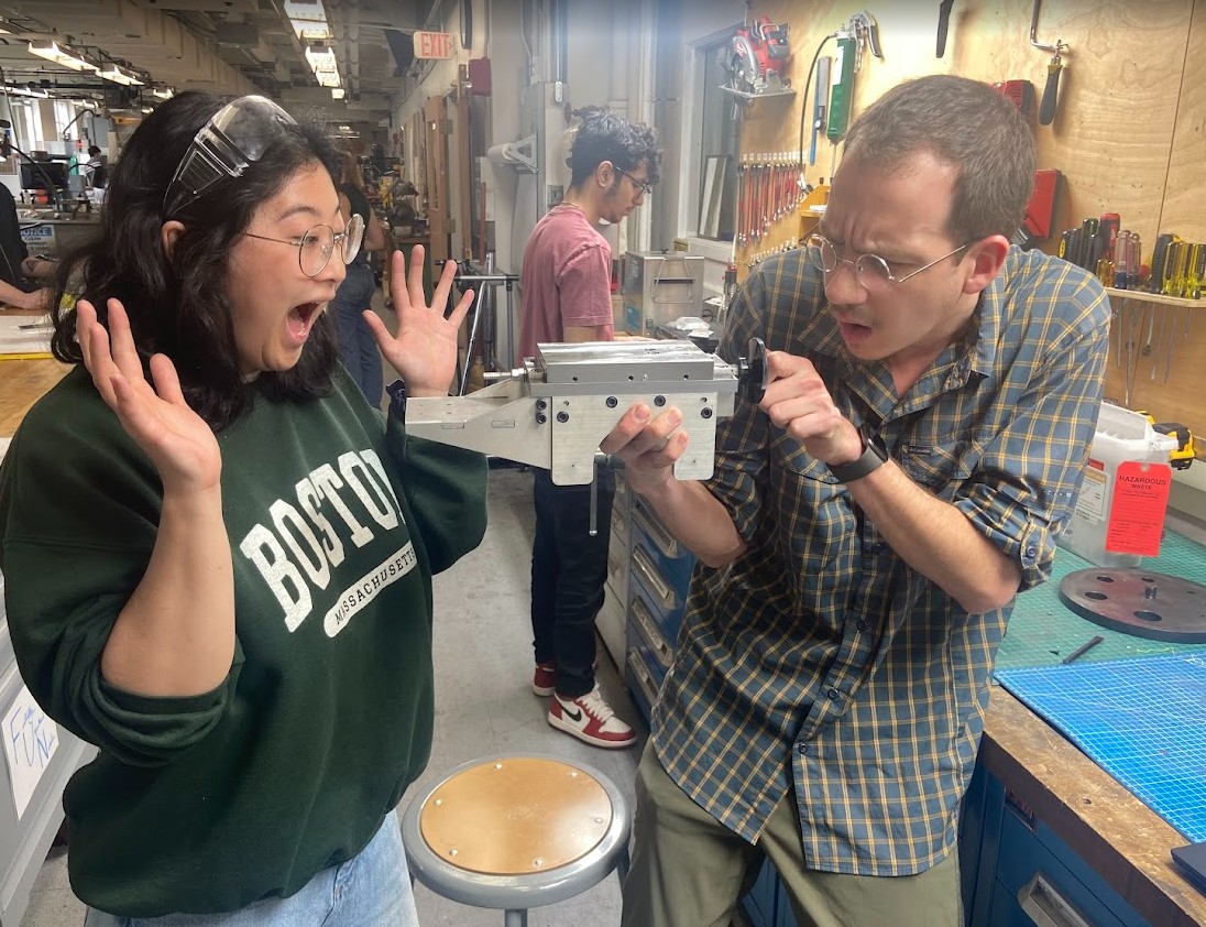
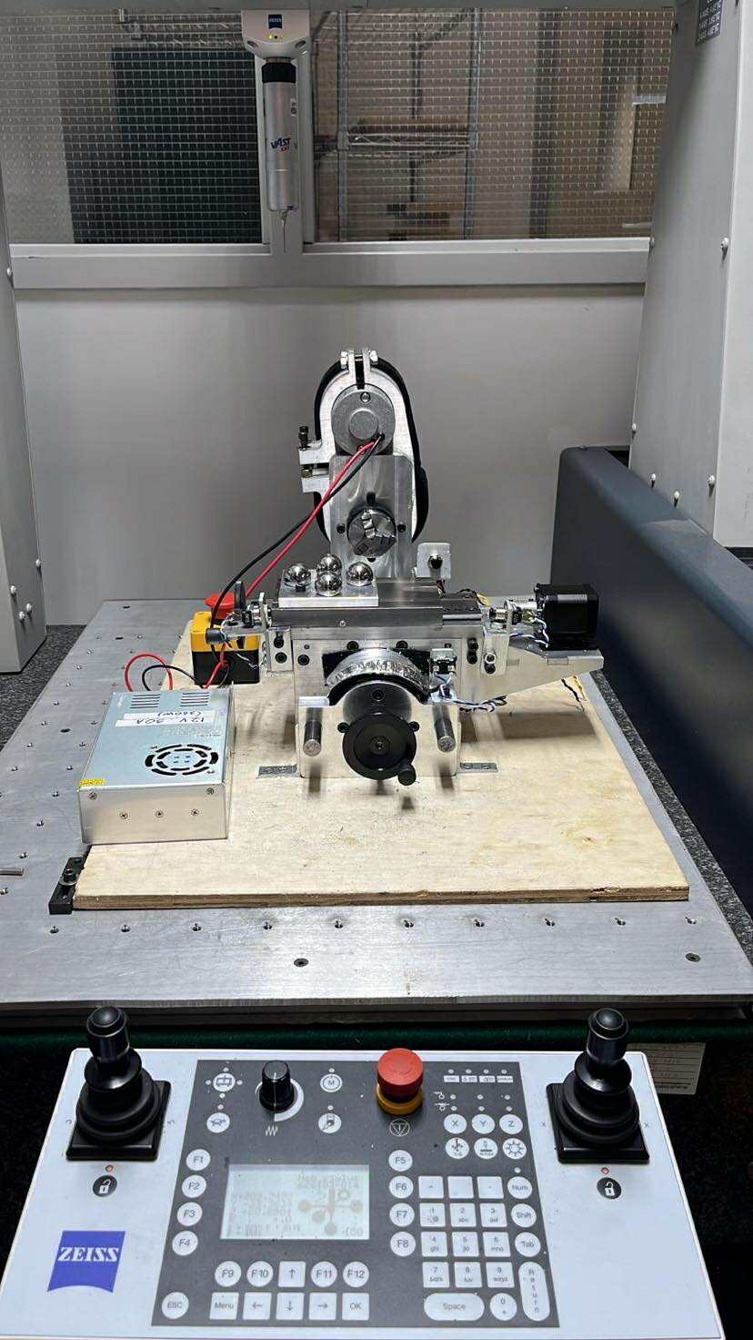
For the final test of the class, Professor Culpepper conducts the "DEATH TEST" where we drop the lathe from table height and hit it with a sledgehammer and confirm that the lathe is still functional!